Showing posts with label ROUTING. Show all posts

How to configure dynamic nat in cisco router using packet tracer step by step guide


How To Configure Dynamic NAT in Cisco Router | In this article we will learn what is dynamic  nat , how to configure dynamic  nat and after configuring verify the dynamic  nat in cisco router using packet tracer software.

Suppose in an organization we have reserved private network (192.168.1.0/24) to use to communicate among the users. If all users want to access to the internet then dynamic nat plays an important role to fulfill this requirement.

Private ip address Range

Class A => 10.0.0.0  to 10.255.255.255
Class B => 172.16.0.0 to 172.31.255.255
Class C=> 192.168.0.0 to 192.168.255.255

 Type of NAT

Three types of nats are available.


What is Dynamic NAT

In the dynamic nat router is configured a pool of ipv4 address . when user want to access to internet then node request to router to mapping public ip address to the corresponding private ipaddress. 

Lab Diagram
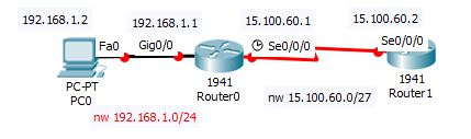
 
How to configure dynamic  nat in cisco router using packet tracer
                           How to configure dynamic  nat in cisco router using packet tracer
In the above diagram we configure dynamic nat in cisco router using packet tracer software.

Configuration of dynamic nating

To configure dynamic nat below some steps we have to follow.

  1. Create a pool of public ip addresses to the router to map the private ip addresses.
  2. Create an access list to permit ip addresses which to be translated.
  3. Map the pool to the access list.
  4. Finally apply nat configuration  to the router interface.

In  the above diagram we have a private network 192.168.1.0/24 which to be mapped to public network which is 15.100.60.0/27. To configure it we follow the below steps.

Router(config)#ip nat pool mypool 15.100.60.3 15.100.60.30 netmask 255.255.255.0
Router(config)#ip access-list extended mypool
Router(config-ext-nacl)#permit ip 192.168.1.0 0.0.0.255 any
Router(config-ext-nacl)#exit
outer(config)#ip nat inside source list mypool pool mypool
Router(config)#int gig0/0
Router(config-if)#ip nat inside
Router(config-if)#exit
Router(config)#int se0/0/0
Router(config-if)#ip nat outside
Router(config-if)#exit
Router(config)#

verify of dynamic nating

After configuring dynamic nating we need to verify it. To verify it we execute the below command.

Router#sh ip nat statistics
Total translations: 0 (0 static, 0 dynamic, 0 extended)
Outside Interfaces: Serial0/0/0
Inside Interfaces: GigabitEthernet0/0
Hits: 0 Misses: 0
Expired translations: 0
Dynamic mappings:
-- Inside Source
access-list mypool pool mypool refCount 0
pool mypool: netmask 255.255.255.0
start 15.100.60.3 end 15.100.60.30
type generic, total addresses 28 , allocated 0 (0%), misses 0

If this article is helpful to know about How To Configure Dynamic NAT in Cisco Router please share and subscribe this article.


Please Donate To Bitcoin Address: [[address]]
Donation of [[value]] BTC Received. Thank You.
[[error]]

HOW TO CONFIGURE EIGRP ON CISCO ROUTER USING PACKET TRACER SOFTWARE STEP BY STEP GUIDE


HOW TO CONFIGURE EIGRP ON CISCO ROUTER USING PACKET TRACER SOFTWARE

In this article we learn how to configure EIGRP and how to verify EIGRP after configuration on cisco router using packet tracer software.

What is EIGRP

EIGRP is called  advanced distance vector and it is  classless protocol. It is a standard protocol and use for cisco and non cisco device, but initially it was cisco proprietary.  It is included all features of igrp. It supports upto 255 hop count and by default it supports upto 100 hop count.

Administrative distance of EIGRP is 90.It does not uses broadcast address .It only uses multicast and unicast address.

By default EIGRP uses bandwidth and delay to calculate the metric calculation.

Lab diagram

HOW TO CONFIGURE EIGRP ON CISCO ROUTER USING PACKET TRACER SOFTWARE

               HOW TO CONFIGURE EIGRP ON CISCO ROUTER USING PACKET TRACER SOFTWARE


In the above diagram we learn the configuration of EIGRP on cisco router using packet tracer software.

Configuration of EIGRP on cisco router using packet tracer

We have to follow two commands to configure EIGRP on cisco router. To enabling the EIGRP we use “router eigrp <AS NO>” (AS is the autonomous system no which should be same ,if as no is different routers can not build eigrp neighbour relationship). Secondly router has to advertise their network to configure the EIGRP.

For router0
#router eigrp 1
#network 10.0.0.0
#network 172.16.0.0


For router1

#router eigrp 1
#network 172.16.0.0
#network 192.168.1.0

verify of EIGRP on cisco router using packet tracer

After configuration we need to verify the configuration whether it is configured successfully or not. To verify the the neighbour table on the router0 we execute the below command.

Router#show ip eigrp neighbors
IP-EIGRP neighbors for process 1
H Address Interface Hold Uptime SRTT RTO Q Seq
(sec) (ms) Cnt Num
0 172.16.0.2 Se0/0/0 13 00:00:42 40 1000 0 4

To verify the topology table from the router0 we execute the below command.

Router#sh ip eigrp topology
IP-EIGRP Topology Table for AS 1/ID(172.16.0.1)

Codes: P - Passive, A - Active, U - Update, Q - Query, R - Reply,
r - Reply status

P 10.0.0.0/8, 1 successors, FD is 5120
via Connected, GigabitEthernet0/0
P 172.16.0.0/16, 1 successors, FD is 2169856
via Connected, Serial0/0/0
P 192.168.1.0/24, 1 successors, FD is 2172416
via 172.16.0.2 (2172416/5120), Serial0/0/0

To verify the routing table from router0 we execute the below command

Router#sh ip route
Codes: L - local, C - connected, S - static, R - RIP, M - mobile, B - BGP
D - EIGRP, EX - EIGRP external, O - OSPF, IA - OSPF inter area
N1 - OSPF NSSA external type 1, N2 - OSPF NSSA external type 2
E1 - OSPF external type 1, E2 - OSPF external type 2, E - EGP
i - IS-IS, L1 - IS-IS level-1, L2 - IS-IS level-2, ia - IS-IS inter area
* - candidate default, U - per-user static route, o - ODR
P - periodic downloaded static route

Gateway of last resort is not set

10.0.0.0/8 is variably subnetted, 2 subnets, 2 masks
C 10.0.0.0/8 is directly connected, GigabitEthernet0/0
L 10.0.0.1/32 is directly connected, GigabitEthernet0/0
172.16.0.0/16 is variably subnetted, 2 subnets, 2 masks
C 172.16.0.0/16 is directly connected, Serial0/0/0
L 172.16.0.1/32 is directly connected, Serial0/0/0
D 192.168.1.0/24 [90/2172416] via 172.16.0.2, 00:04:12, Serial0/0/0

Thanks for learning this article. If you like this article please like ,share and comment for this article.   

Please Donate To Bitcoin Address: [[address]]

Donation of [[value]] BTC Received. Thank You.
[[error]]

Intoroduction of EIGRP and how EIGRP works


Intoroduction of EIGRP

In this article we learn about the feature of EIGRP ,how EIGRP works and in the next part we learn the configuration of EIGRP for demotration purpose using packet tracer software.

Feature of EIGRP

EIGRP is called  advanced distance vector and it is  classless protocol. It is a standard protocol and use for cisco and non cisco device, but initially it was cisco proprietary.  It is included all features of igrp. It supports upto 255 hop count and by default it supports upto 100 hop count.

Administrative distance of EIGRP is 90.It does not uses broadcast address .It only uses multicast and unicast address.

By default EIGRP uses bandwidth and delay to calculate the metric calculation.

Type of EIGRP table

There are three types of tables which EIGRP protocol uses.
·         Neighbour table

To show the neighbour table we use the below command.
#show ip eigrp neighbour

·         Topology table

To show the topology table we use the below command.
#show ip eigrp topology

·         Routing table.

To show the routing table we use the below command
#show ip route


How EIGRP works

In this section we learn how to EIGRP works.
Suppose we have two routers.

STEP1: when router1 is advertising its interface then it send a hello packet to router2 using 224.0.0.10 multicast address. Router2 can not understand the the message unless it advertise its interface. After router2 advertises ites interface it also send a hello message to router1 using unicast address. After exchanging hello messages they build a neighbour table.

STEP2:  After established the neighbour table they exchange their routing information to each other and select the all best path and build a topology table.

STEP3:  After completing step2 they chose the top best route among the best routes and build a routing table.

Intoroduction of EIGRP

                                       Intoroduction of EIGRP


How to configure nat overload in cisco router using packet tracer step by step guide


In this article we will  learn what is  nat overload(PAT), how to configure  nat overload in cisco router using packet tracer software.

Normally we use private ip inside the organization which is not allow to users to access the internet,then we use dynamic nat to fulfill our purpose. If ISP not provides organization pool of ip address then we go the another option which is called NAT overload(PAT).

Private ip address Range

Normally we use private ip address which is reserved inside the organization to communicate internal purpose which is not public ip address. The ange are given below.

Class A => 10.0.0.0  to 10.255.255.255
Class B => 172.16.0.0 to 172.31.255.255
Class C=> 192.168.0.0 to 192.168.255.255

Type of NAT

Three types of nats are available.


What is NAT overload

In the dynamic nating we saw that ISP provides us a pool of public ip address to map with internal private ip to access internet. If ISP gives us few public ip addresses or 1 public ip address instead a pool of public ip addresses to map internal private ip addresses to access internet. In this scenario NAT overload is configured to overcome the problem.

Lab Diagram

How to configure nat overload in cisco router using packet tracer

                         How to configure nat overload in cisco router using packet tracer


In the above diagram we configure nat overload in cisco router using packet tracer software.

Configuration of NAT overload(PAT)

If ISP gives us few ip addresses or even 1 ip address so we can eliminate the netmask keyword from the dynamic nating command.

Router(config)#ip nat pool mypool 15.100.60.3 15.100.60.4
Router(config)#ip access-list extended mypool
Router(config-ext-nacl)#permit ip 192.168.1.0 0.0.0.255 any
Router(config-ext-nacl)#exit

Here we use only two public ip addesses to map with the internal private ip addresses.Finally we bind the access list with pool and use overload keyword end of the command.

Router(config)#ip nat pool inside source list mypool pool mypool overload


In this article we have   learned what is  nat overload(PAT), how to configure  nat overload in cisco router using packet tracer software.


RIP protocol configuration guide example on packet tracer step by step guide

Summary

RIP protocol configuration commands | In this article we will learn about the definition of RIP protocol ,how to configure RIP protocol in packet tracer on cisco router ,after configuration how to verify RIP protocol is successfully configured or not. In this articles we demonstrate the configuration of routing information protocol(version 1) with two cisco routers on packet tracer.

What is Routing Information Protocol(RIP protocol)

Routing Information Protocol is a distance vector protocol. It uses hop count as a routing metric. By default administrative distance of RIP is 120.Rip protocol uses maximum 15 hop counts.RIP protocol updates it's routing table after every 30 seconds.

What is hop count

We can calculate hop count using how many hops rip protocol will cover to reach destination router from the source router. Rip protocol always calculate minimum hops as a best path to reach destination router. Rip protocol uses maximum 15 hops .Rip protocol will be unreachable after 15 hops.

Lab Diagram

RIP protocol configuration guide example on packet tracer

RIP protocol configuration guide example on packet tracer


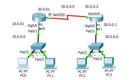
In the above diagram we use two cisco routers to demonstrate Ripv1 configuration.

Configuration of Routing Information Protocol

To configure RIP protocol first we assign ip address of the interface of those two routers and assign clock rate to the serial interface at DCE side. After assigning the ip address we will start the configuration part of routing information protocol.
We assign the interface ip and clock rate on router0 interface to execute the below command.
Router#conf t
Enter configuration commands, one per line. End with CNTL/Z.
Router(config)#int gigabitEthernet 0/0
Router(config-if)#ip address 10.0.0.1 255.0.0.0
Router(config-if)#no shut
Router(config-if)#exit
Router(config)#int serial 0/0/0
Router(config-if)#clock rate 64000
Router(config-if)#ip address 20.0.0.1 255.0.0.0
Router(config-if)#no shut

We assign the interface ip on router1 interface to execute the below command.
Router#conf t
Enter configuration commands, one per line. End with CNTL/Z.
Router(config)#int gigabitEthernet 0/0
Router(config-if)#ip address 30.0.0.1 255.0.0.0
Router(config-if)#no shut
Router(config-if)#exit
Router(config)#int serial 0/0/0
Router(config-if)#ip address 20.0.0.2 255.0.0.0
Router(config-if)#no shut
After completed the above configuration we are going to the second part of the configuration which is rip configuration. To configure rip protocol on router0 we execute the below command on router0.
Router(config)#router rip
Router(config-router)#version 1
Router(config-router)#network 30.0.0.0
Router(config-router)#network 20.0.0.0
Router(config-router)#network 10.0.0.0
Router(config-router)#exit
To configure rip on router1 we execute the below command on router1.
Router(config)#router rip
Router(config-router)#version 1
Router(config-router)#network 30.0.0.0
Router(config-router)#network 20.0.0.0
Router(config-router)#network 10.0.0.0
Router(config-router)#exit

Verify configuration of Routing Information Protocol

After completed the above configuration we need to verify RIP protocol whether it is successfully configured or not.we are using the below command to verify it on both routers.
Router#sh ip route
Codes: L - local, C - connected, S - static, R - RIP, M - mobile, B - BGP
D - EIGRP, EX - EIGRP external, O - OSPF, IA - OSPF inter area
N1 - OSPF NSSA external type 1, N2 - OSPF NSSA external type 2
E1 - OSPF external type 1, E2 - OSPF external type 2, E - EGP
i - IS-IS, L1 - IS-IS level-1, L2 - IS-IS level-2, ia - IS-IS inter area
* - candidate default, U - per-user static route, o - ODR
P - periodic downloaded static route

Gateway of last resort is not set

10.0.0.0/8 is variably subnetted, 2 subnets, 2 masks
C 10.0.0.0/8 is directly connected, GigabitEthernet0/0
L 10.0.0.1/32 is directly connected, GigabitEthernet0/0
20.0.0.0/8 is variably subnetted, 2 subnets, 2 masks
C 20.0.0.0/8 is directly connected, Serial0/0/0
L 20.0.0.1/32 is directly connected, Serial0/0/0
R 30.0.0.0/8 [120/1] via 20.0.0.2, 00:00:01, Serial0/0/0
When we are going to communicate from pc0 to pc2 we got the reply message.
C:\>ping 30.0.0.2

Pinging 30.0.0.2 with 32 bytes of data:

Request timed out.
Reply from 30.0.0.2: bytes=32 time=1ms TTL=126

Ping statistics for 30.0.0.2:
Packets: Sent = 4, Received = 3, Lost = 1 (25% loss),
Approximate round trip times in milli-seconds:
Minimum = 1ms, Maximum = 1ms, Average = 1ms

Conclusion


In this article we have learned about the definition of RIP protocol ,how to configure RIP protocol in packet tracer on cisco router ,after configuration how to verify RIP protocol is successfully configured or not. In this articles we demonstrate the configuration of routing information protocol(version 1) with two cisco routers on packet tracer. If this article is helpful to know about RIP protocol Configuration please share this.


Default Routing lab using packet tracer with step by step guide


Configuration of Default Routing |In this article we learn about the concept of default routing and how to configure default routing and after configuration we will see how to verify default routing.

What is Default routing

It is one type of static routing. Default routing is the routing method when packets are send to the destination which is not listed in the routing tables. Basically default routing is in the stub network.
Stub network is the network which has one exit point, that means all routers in the network are configured to send the packet to a single router which is the gateway of this network.

Lab Diagram

Default Routing lab using packet tracer

In the above diagram we will be configure the default routing using three routers.

Configuration of Default Routing

First we configure on router0.
Router#conf t
Enter configuration commands, one per line. End with CNTL/Z.
Router(config)#int gigabitEthernet 0/0
Router(config-if)#ip address 10.0.0.1 255.0.0.0
Router(config-if)#no shut
Router(config)#int serial 0/0/0
Router(config-if)#clock rate 64000
Router(config-if)#ip address 20.0.0.1 255.0.0.0
Router(config-if)#no shut

To configure static route on router0 we should execute the below command.
Router(config)#ip route 0.0.0.0 0.0.0.0 20.0.0.2

Then we configure on router1.
Router#conf t
Enter configuration commands, one per line. End with CNTL/Z.
Router(config)#int gigabitEthernet 0/0
Router(config-if)#ip address 30.0.0.1 255.0.0.0
Router(config-if)#no shu

Router(config)#int serial 0/0/0
Router(config-if)#ip address 20.0.0.2 255.0.0.0
Router(config-if)#no shut

Router(config)#int serial 0/0/1
Router(config-if)#ip address 40.0.0.1 255.0.0.0
Router(config-if)#no shut

To configure static route on router1 we should execute the below command.
Router(config)#ip route 0.0.0.0 0.0.0.0 20.0.0.1
Router(config)#ip route 0.0.0.0 0.0.0.0 40.0.0.2


Then we configure on router2.
Router#conf t
Enter configuration commands, one per line. End with CNTL/Z.
Router(config)#int gigabitEthernet 0/0
Router(config-if)#ip address 50.0.0.1 255.0.0.0
Router(config-if)#no shut

Router(config)#int serial 0/0/0
Router(config-if)#clock rate 64000
Router(config-if)#ip address 40.0.0.2 255.0.0.0
Router(config-if)#no shut

To configure static route on router2 we should execute the below command.
Router(config)#ip route 0.0.0.0 0.0.0.0 40.0.0.1


Verify default route

To verify the default route we execute the below command on router0
Router#sh ip route
Codes: L - local, C - connected, S - static, R - RIP, M - mobile, B - BGP
D - EIGRP, EX - EIGRP external, O - OSPF, IA - OSPF inter area
N1 - OSPF NSSA external type 1, N2 - OSPF NSSA external type 2
E1 - OSPF external type 1, E2 - OSPF external type 2, E - EGP
i - IS-IS, L1 - IS-IS level-1, L2 - IS-IS level-2, ia - IS-IS inter area
* - candidate default, U - per-user static route, o - ODR
P - periodic downloaded static route

Gateway of last resort is 20.0.0.2 to network 0.0.0.0

10.0.0.0/8 is variably subnetted, 2 subnets, 2 masks
C 10.0.0.0/8 is directly connected, GigabitEthernet0/0
L 10.0.0.1/32 is directly connected, GigabitEthernet0/0
20.0.0.0/8 is variably subnetted, 2 subnets, 2 masks
C 20.0.0.0/8 is directly connected, Serial0/0/0
L 20.0.0.1/32 is directly connected, Serial0/0/0
S* 0.0.0.0/0 [1/0] via 20.0.0.2

To verify the default route we execute the below command on router1
Router#sh ip route
Codes: L - local, C - connected, S - static, R - RIP, M - mobile, B - BGP
D - EIGRP, EX - EIGRP external, O - OSPF, IA - OSPF inter area
N1 - OSPF NSSA external type 1, N2 - OSPF NSSA external type 2
E1 - OSPF external type 1, E2 - OSPF external type 2, E - EGP
i - IS-IS, L1 - IS-IS level-1, L2 - IS-IS level-2, ia - IS-IS inter area
* - candidate default, U - per-user static route, o - ODR
P - periodic downloaded static route

Gateway of last resort is 20.0.0.1 to network 0.0.0.0

20.0.0.0/8 is variably subnetted, 2 subnets, 2 masks
C 20.0.0.0/8 is directly connected, Serial0/0/0
L 20.0.0.2/32 is directly connected, Serial0/0/0
30.0.0.0/8 is variably subnetted, 2 subnets, 2 masks
C 30.0.0.0/8 is directly connected, GigabitEthernet0/0
L 30.0.0.1/32 is directly connected, GigabitEthernet0/0
40.0.0.0/8 is variably subnetted, 2 subnets, 2 masks
C 40.0.0.0/8 is directly connected, Serial0/0/1
L 40.0.0.1/32 is directly connected, Serial0/0/1
S* 0.0.0.0/0 [1/0] via 20.0.0.1
[1/0] via 40.0.0.2
To verify the default route we execute the below command on router2
Router#sh ip route
Codes: L - local, C - connected, S - static, R - RIP, M - mobile, B - BGP
D - EIGRP, EX - EIGRP external, O - OSPF, IA - OSPF inter area
N1 - OSPF NSSA external type 1, N2 - OSPF NSSA external type 2
E1 - OSPF external type 1, E2 - OSPF external type 2, E - EGP
i - IS-IS, L1 - IS-IS level-1, L2 - IS-IS level-2, ia - IS-IS inter area
* - candidate default, U - per-user static route, o - ODR
P - periodic downloaded static route

Gateway of last resort is 40.0.0.1 to network 0.0.0.0

40.0.0.0/8 is variably subnetted, 2 subnets, 2 masks
C 40.0.0.0/8 is directly connected, Serial0/0/0
L 40.0.0.2/32 is directly connected, Serial0/0/0
50.0.0.0/8 is variably subnetted, 2 subnets, 2 masks
C 50.0.0.0/8 is directly connected, GigabitEthernet0/0
L 50.0.0.1/32 is directly connected, GigabitEthernet0/0
S* 0.0.0.0/0 [1/0] via 40.0.0.1

If this article is helpful to know Configuration of Default Routing please share this article.